A state-based security system built on the Arduino UNO (Elegoo kit) that integrates a membrane keypad, IR remote, and RFID-RC522 reader — with a Python GUI for real-time tag logging.
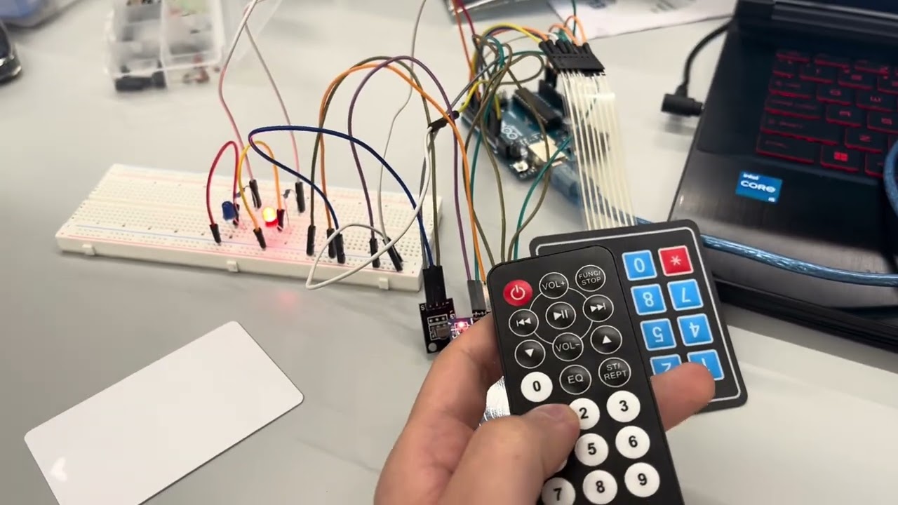

This project implements a complete lock and tag-logging pipeline:
- A 4-digit PIN is entered on the keypad to lock the system
- The same PIN entered via IR remote unlocks it
- In the unlocked state, the RFID-RC522 actively listens for tags
- Each scan is logged to a SQLite database via Serial
- A Python/Tkinter GUI displays the tag database in real time
┌─────────┐   Keypad PIN (#)   ┌────────┐   IR PIN (match)   ┌──────────┐
│ WAITING │ ─────────────────► │ LOCKED │ ──────────────────► │ UNLOCKED │
│  LED A  │                    │ LED B  │                     │ LED A+B  │
└─────────┘                    └────────┘                     └──────────┘
                                                                    │
                                                              RFID active
                                                              Tags logged
| State | LED A | LED B | Keypad | IR Remote | RFID |
|---|---|---|---|---|---|
WAITING |
ON | OFF | ✅ Set PIN | ❌ | ❌ |
LOCKED |
OFF | ON | ❌ | ✅ Enter PIN | ❌ |
UNLOCKED |
ON | ON | ❌ | ❌ | ✅ Active |
| Component | Elegoo Kit Part |
|---|---|
| Arduino UNO R3 | Included |
| 4×4 Membrane Switch Keypad | Included |
| IR Receiver Module + Remote | Included |
| RFID-RC522 Module | Included |
| 2× LEDs (any color) | Included |
| 2× 220Ω Resistors | Included |
| Breadboard + Jumper Wires | Included |
KEYPAD (4×4)
─────────────────────────────────────
 Row 1  →  Pin 9
 Row 2  →  Pin 8
 Row 3  →  Pin 7
 Row 4  →  Pin 6
 Col 1  →  Pin 5
 Col 2  →  Pin 4
 Col 3  →  Pin 3
 Col 4  →  Pin 2

IR RECEIVER MODULE
─────────────────────────────────────
 Signal →  Pin A2
 VCC    →  5V
 GND    →  GND

LEDs
─────────────────────────────────────
 LED A  →  Pin A0  →  220Ω  →  GND
 LED B  →  Pin A1  →  220Ω  →  GND

RFID-RC522          ⚠️  3.3V ONLY — do not use 5V
─────────────────────────────────────
 SDA    →  Pin 10
 SCK    →  Pin 13
 MOSI   →  Pin 11
 MISO   →  Pin 12
 RST    →  Pin A3
 3.3V   →  3.3V
 GND    →  GND
⚠️ Warning: The RC522 is a 3.3V module. Supplying 5V will permanently damage it.
Install all three via Arduino IDE → Tools → Manage Libraries:
| Library | Author | Version |
|---|---|---|
Keypad |
Mark Stanley / Alexander Brevig | Any |
IRremote |
shirriff et al. | 2.x (not v3/v4) |
MFRC522 |
GithubCommunity | Any |
pip install pyserial
tkinterandsqlite3are included in the Python standard library.
Every IR remote has different hex codes for each button. Before uploading the main sketch, you must map your remote's digit codes.
Quick calibration sketch:
#include <IRremote.h>
IRrecv irrecv(A2);
decode_results results;

void setup() {
  Serial.begin(9600);
  irrecv.enableIRIn();
}

void loop() {
  if (irrecv.decode(&results)) {
    Serial.println(results.value, HEX);
    irrecv.resume();
  }
}- Upload this sketch
- Open Serial Monitor (9600 baud)
- Press digits 0–9 on your remote and note the hex codes
- Fill in the
IR_CODES[10]array infirmware/security_system.ino
- Open
firmware/security_system.inoin Arduino IDE - Select Board: Arduino UNO and the correct Port
- Verify IR codes are filled in (step 1)
- Click Upload
- Open Serial Monitor to confirm
SYSTEM:READYis printed
Using the system:
- Type 4 digits on the keypad, press
#to lock - Press
*on the keypad to clear your input - Type the same 4 digits via IR remote to unlock
- Present an RFID card/fob — LEDs flash, tag is logged
cd python
python gui.py
⚠️ Close the Arduino Serial Monitor before running the Python script — both cannot share the serial port simultaneously.
The script auto-detects your Arduino's COM port. If detection fails, edit line 72 in gui.py:
port = "COM3"       # Windows
# port = "/dev/ttyUSB0"  # Linux
# port = "/dev/cu.usbmodem14101"  # macOS
The GUI shows a live table of scanned tags:
| Column | Description |
|---|---|
| ID | Auto-incremented unique ID |
| UID | RFID tag identifier (hex) |
| First Seen | Timestamp of first scan |
| Last Seen | Timestamp of most recent scan |
| Scan Count | Total number of times this tag was scanned |
arduino-security-system/
│
├── firmware/
│   └── security_system.ino      # Arduino sketch
│
├── python/
│   ├── gui.py                   # Tkinter GUI + serial listener
│   └── rfid_log.db              # SQLite database (auto-created)
│
├── docs/
│   └── wiring_diagram.png       # (optional: photo of your wiring)
│
└── README.md
| Problem | Likely Cause | Fix |
|---|---|---|
| RFID not reading | RC522 wired to 5V | Move VCC to 3.3V pin |
| IR not recognized | Wrong hex codes | Re-run calibration sketch |
| Python can't open port | Serial Monitor still open | Close Arduino IDE Serial Monitor |
| Python can't open port | Wrong port | Edit port variable in gui.py |
| Keypad not responding | Row/col pins swapped | Double-check rowPins[] / colPins[] |
| Tags not logged to DB | State not UNLOCKED | Unlock system first via IR remote |
| IRremote compile error | Wrong library version | Downgrade to IRremote v2.x |
Rashad — Computer Engineering, ADA University (Class of 2026)
GitHub · LinkedIn